A hat full of electrometers - Mass production
A bunch of electrometers in need of a hat.
A hat full of electrometers - Table of Contents
I started this project last year, a couple of months too late to be used on Halloween - even though it was intended for Halloween.
Here it is nearly Halloween again, so I thought it was about time to get on it and get it done.
I’ve been intending to use my Adler sewing machine to make the hat band, but that’s taking longer than planned. There’s been too much other stuff going on, so the new base for the machine isn’t finished yet. I can either finish the sewing machine or finish the hat band before Halloween. Nobody’s waiting on the sewing machine, but I expect my daughter would like to have her hat band in time to use it this year.
I actually assembled the electrometers in December of last year. They’ve spent the last ten months patiently waiting for me to do something with them.
First off, a look at how the electrometers were assembled.
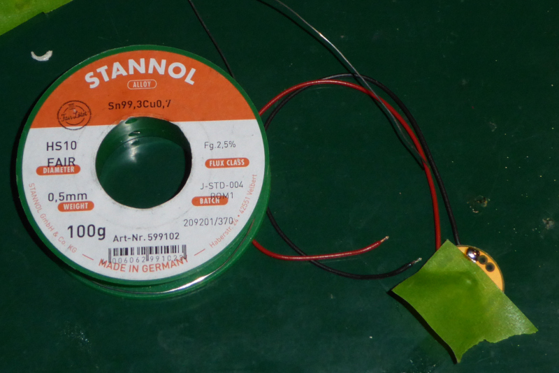
As I mentioned in my last post, the only really tricky part was not messing up the bare, gold plated front while soldering the LEDs. The way around that is to tape off the gold parts with frog tape. It sticks to the PCBs very nicely, it doesn’t burn if you bump it with the soldering iron, it keeps the solder from flowing into places it doesn’t belong, and it peels off easily when done.
I’ve intentionally messed up one of my spares to show you how well frog tape works as a removable solder mask:
| Frog tape as solder mask |
|---|
 |
 |
There’s a nice, clean edge where the tape was. Not even flux got underneath it.
Note also that I’m using lead free solder at about 350 degree C. Not even that (relatively) high temperature could bother the frog tape.
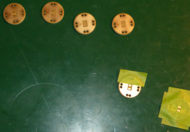
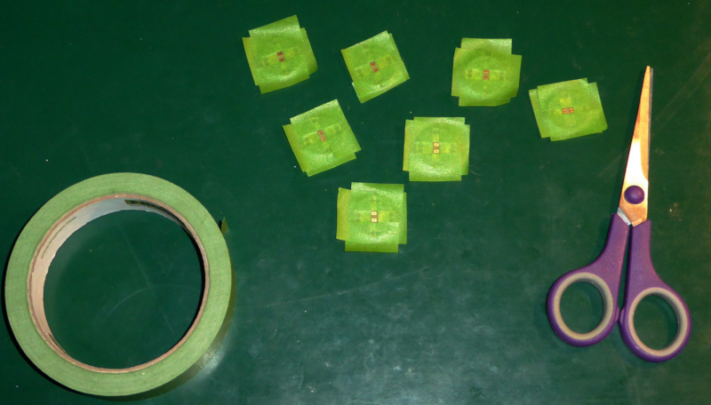
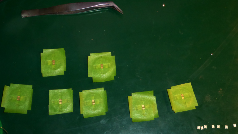
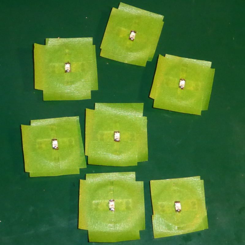
I taped up all of the electrometers at once before I got out the soldering iron.
| Taped electrometers |
|---|
 |
 |
I soldered the back sides first:
| Back side |
|---|
 |
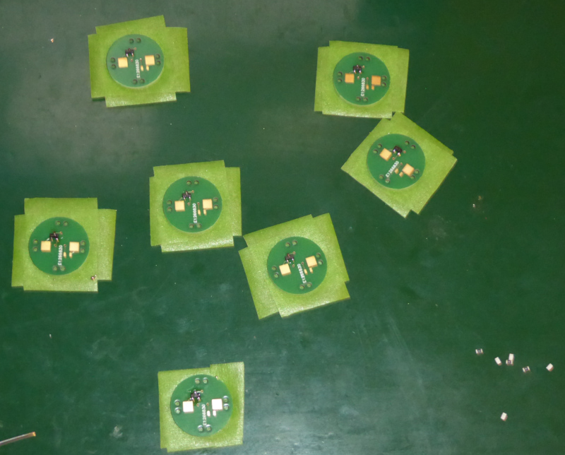 |
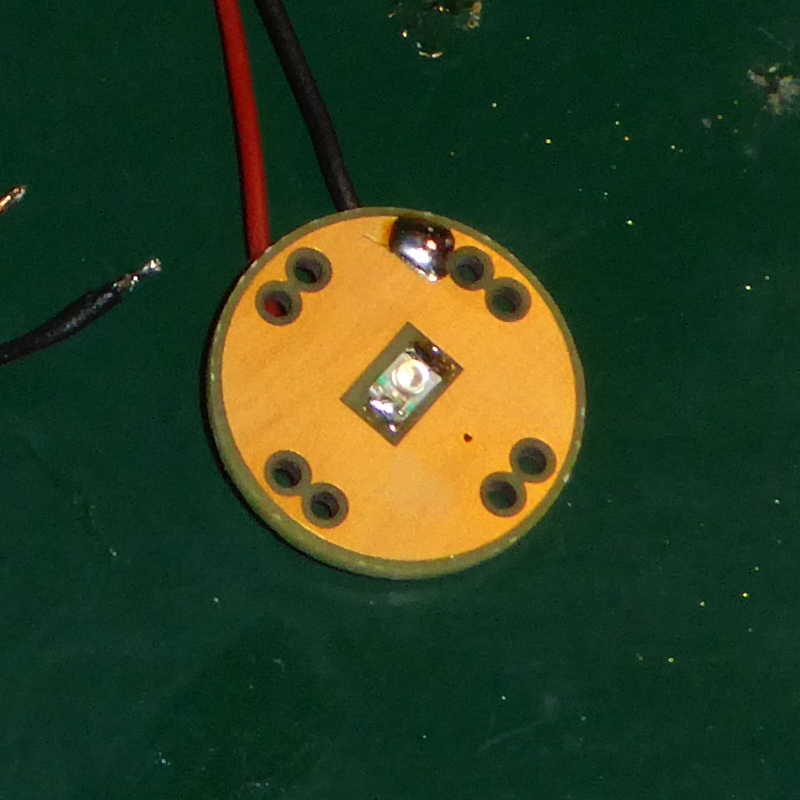
The LEDs went on last:
| Front side |
|---|
 |
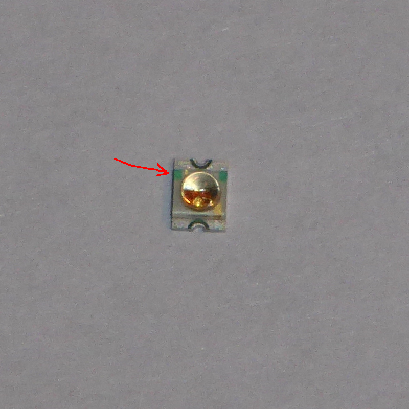 |
There was one little bit of trickiness left on the LEDs. Which way around do they go? My LEDs have little green markings (where the red arrow points) to mark the anode. That goes towards the positive side of the circuit. The unmarked contact goes to the ground side of the circuit. The datasheet for your LEDs will tell you how they are marked.
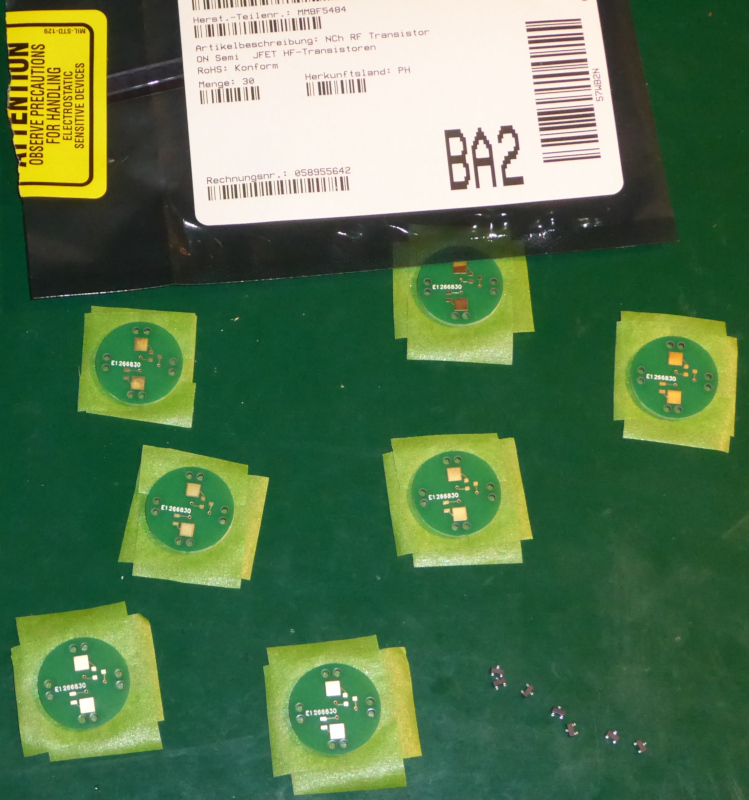
Here they are all together. Just a bunch of electrometers looking for a hat:
| Finished electrometers |
 |
I hooked all of the eletrometers up to make sure they work:
| All on |
|---|
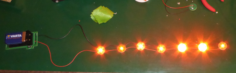 |
I scuffed my feet on the floor then waved my hand at the electrometers and made some of them go off:
| Working eletrometers |
|---|
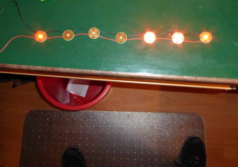 |
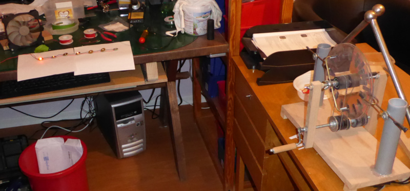
After that, I poked them all with my fingers to make them come back on. When they were all lit up again, I put my Wimshurst machine about a meter away and cranked it. The eletrometers started going out, the closest ones first:
| Turned off from a distance |
|---|
 |
They all work.
The next task is to make the hat band itself. Once that’s done, I can thread the wiring for the electrometers through it and solder things all together.
Tomorrow, or maybe on Sunday. That’s enough for today.