Generating extreme low frequency signals with a PC and an audio amplifier
I don’t need this, but I did it anyway.
While making the persistence mode for my D43 oscilloscope camera software and playing with the amplitude modulated Greinacher voltage multiplier, I realized that I had hit upon a way to generate extremely low frequency signals using a PC.
The signals I was working with were down around 10Hz. That’s already at (or below) what a typical PC sound card can produce. I wasn’t so much interested in the low frequencies as in a method for multiplying an audio signal with a voltage multiplier. The equipment I have won’t work at the high frequencies I would really need to make it work, so I was using lower frequencies to simulate a high frequency system.
I needed the persistence mode to make some decent pictures of the simulated signals with my old analog oscilloscope.
To test the persistence mode, I lowered the output frequency of my test setup to generate a sine wave with a period of 24 seconds. That’s 42 millihertz.
Yes, 42 millihertz out of the sound card output of my PC.
Well, almost.
I did have a regular audio amplifier in there, and a voltage multiplier besides that.
What I’m doing is generating a high frequency audio signal (16kHz) and modulating it with an extreme low frequency signal. Both signals are generated in software, and the modulation is done in the software as well.
The output from the PC looks something like this:
| Modulated output |
|---|
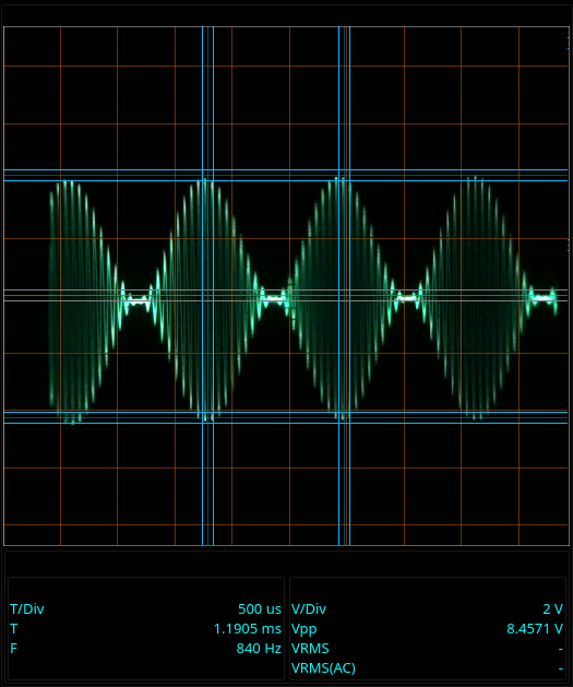 |
That’s actually an 840Hz signal modulated on to a 16kHz carrier. It’s easier to see the waves that way than with the signals I really used. The carrier looks like a solid area on the oscilloscope screen when using a 16kHz carrier and 1Hz modulating signal.
What I do is generate that signal in the PC, then send it through line out to an audio amplifier that puts out a signal at about 9V peak to peak.
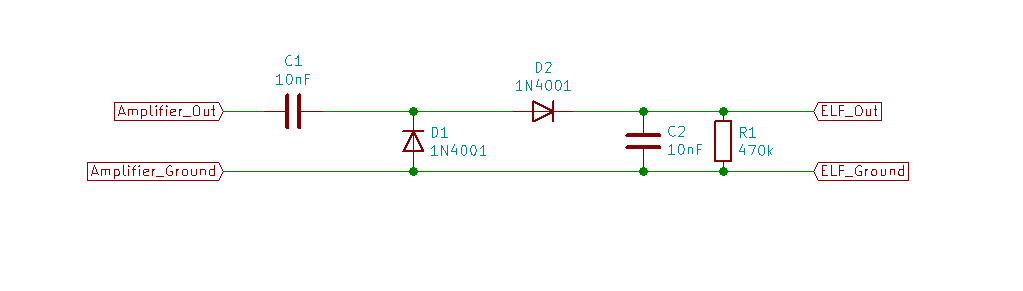
From the amplifier, the signal goes into a “demodulator.” The demodulator is a Greinacher voltage doubler.
Most folks think of voltage multipliers as generating DC, but the fact is that the output is some multiple of the input. If the input level changes, so does the output level.
The voltage multiplier I’m using as a demodulator has been tweaked a little to make it track the input better - up to a limit. With the values I’m using, you can get a nearly undistorted signal up to about 10Hz. Above that, the output can’t track the input properly any more and the demodulated signal is distorted.
Here’s the demodulator I used:
| Demodulator circuit |
|---|
 |
The cool thing is that any frequency below 10Hz works just fine. It goes all the way down to DC - I mean, it is a voltage multiplier and they are known for generating DC.
Need to generate a 30 day sine wave? The software can do it, and if your amplifier is that stable then you can get that long period sine wave out of the demodulator.
I don’t have the patience (or any equipment to record and analyze a signal that slow) but I have run signals down to several minutes.
When I decided to write this post, I figured it would only be polite to post the software as well.
I intended to clean it up a bit and then post it, and ended up spending several hours yesterday improving it and tidying it up.
If you’d like to use it, then you’ll need Pure Data.
I recommend the Purr Data package. There’s a Windows and Mac version available at the link. Linux users can get it through the package management system of whatever distribution you use. Purr Data brings a lot of additional functions with it that the original Pure Data doesn’t. You can get all of the addons at various places around the internet, but Purr Data has them all collected and ready for use.
Pure Data is a sort of a graphical programming language centered around manipulating audio signals. Sort of like GNU Radio except it’s for audio rather than radio - and that Pure Data has been around longer. GNU Radio was first published in 2001, while Pure Data has been around since 1996.
I any case, I posted the Pure Data “patch” for the extreme low frequency signal generator on github after cleaning it up.
The GUI looks like this:
| Signal generator GUI |
|---|
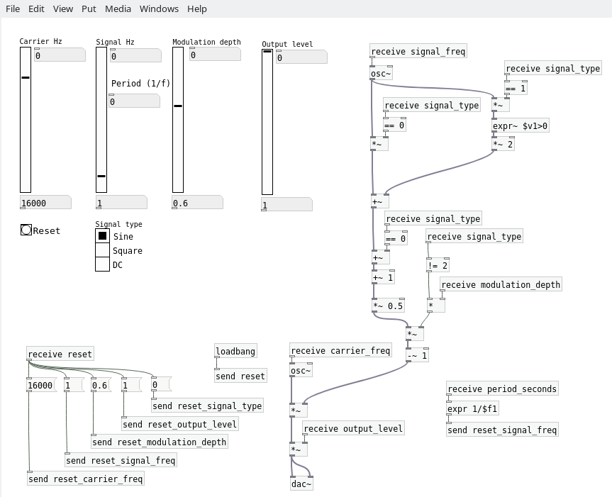 |
I intentionally left the “guts” hanging out.
I find it fun to work with Pure Data because you can change things live. Need an amplifier? Break a trace and insert a multiplier block. Need another oscillator? Drop one down and add it to your output. No stopping, no compiling, just keep adding things and twiddling around.
With the guts hanging there next to the GUI, it sort of invites me to play with it and make it do new things. I spent literally hours yesterday staring at the oscilloscope output and monkeying around with the patch.
I added a square wave generator, and a DC output while fiddling with things. Well, why not?
There are no voltages marked, of course. The output level depends on the volume control of your PC. It depends on the output level of your amplifier. There’s no practical way to calibrate that. You just have to adjust the controls and measure the output level.
One thing that helps is that the demodulated output level is almost completely independent of the frequency. You can set the output to a “high” frequency (like, 5Hz) to adjust the level settings then switch to your 5 day period sine wave and the level will stay the same.
Now that it’s done, I have no use for the silly thing. I built it because I already had most of it done. I extended the software because Pure Data just invites playing around with things. Now what do I do with it? Nothing, I don’t need it. I give it to you in the hopes that someone, somewhere has a use for this oddball thingamabob.
Do you have a need for extremely low frequency signals?
What are you working on?
Drop me a line in the comments if you found this useful in anyway.