HowTo: Solder by hand - An introduction
Learn a basic skill for your electronics hobby.
Skip straight to the table of contents if you are in a hurry.
If you build electronics projects, you will eventually reach a point where a solderless breadboard just won’t do any more. You’ll either need or want to make something more permanent. Or, maybe you’ll buy a kit to build something that you can’t yet design on your own.
In any case, a permanent circuit usually translates to a printed circuit board (PCB) with the parts soldered on.
At this point, you’ll have to learn to solder.
Back when I learned to solder as a kid, all I had to go on were drawings and descriptions in books I borrowed from the school library. They weren’t all that good, but I got the idea somehow and managed to get pretty good at it.
You’d think things were better today, what with the internet and YouTube.
You’d be wrong.
Written tutorials are few and far between - good ones are even scarcer. I’m no friend of learning from YouTube videos - those tend to be of even lower quality than the written tutorials. In most cases, the drawings or photos (or video sequences) don’t show you what things really look like while you are working. The pictures are from a different angle, or the drawings are generic sketches - and the videos may have started out high resolution, but YouTube squeezes them to the point of fuzzy uselessness. I find written explanations easier to follow than videos, in any case. I can scan rapidly back and forth to compare the text, the pictures, and the reality much faster in a written lesson than I can scrub through a video trying to find the passage I need to listen to again.
Then there’s the whole subject of surface mount devices (SMD) - those itty little tiny parts only a few millimeters long and wide that have replaced the larger through hole parts that I grew up with. Somehow, folks have gotten the idea that SMD parts are hard to solder and otherwise work with. Fact is, I’ve quit using through hole parts. Anything I make these days is all SMD except for connectors or specialty parts that only come in through hole packages. SMD parts are in fact much easier to work with than the old through hole parts. I solder them all by hand. I don’t own a reflow oven or a tube of solder paste. Just a beat up, cheap soldering iron from the hardware store and regular solder - I don’t even own a bottle of flux.
The subject comes up periodically over on the Electrical Engineering Stack Exchange, and it showed up in real life a couple of weeks ago when a person I work with cussed about how difficult it is to learn how to solder.
Since I’m pretty good at it (I spent over 10 years working as an electronics technician,) I thought I’d write up my experiences and show how it is done.
To that end, I built the “Box o’ Buttons” and wrote the EyeGore software and built the EyeGore camera so that I can make photos showing exactly what things should look like when you solder.
Just so you know I’m not talking through my hat, here’s a couple of photos of a project I designed and built a few months ago:
| RF Concho - hand soldered SMD parts |
|---|
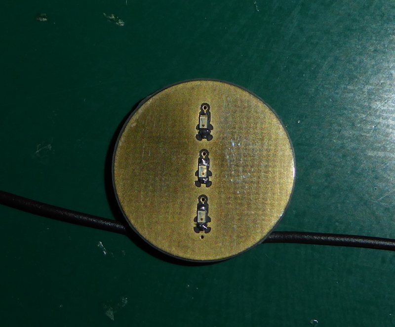 |
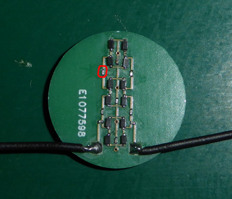 |
See that little thingy I circled in red? That is a 0201 sized SMD capacitor. Wikipedia says that those parts are 0.25 millimeters by 0.125 millimeters in size (that’s 0.01 by 0.005 inches.) I soldered it and all the other parts in those pictures by hand. If you follow the instructions in this series (and practice,) then you will be able to solder like that as well.
I’m going to make a series of blog posts over the next few days that will take you from getting the needed equipment all the way to soldering 0201 sized SMD parts.
I’m going to link all of the posts in a single table of contents to organize things. For now, it is just a list of the things I plan to write about. Come back by and check again - I’ll update it as I go along.
For now, I’m going to take a break. I was up way too late last night finishing up EyeGore.