A sewing machine motor speed control - Musings on motor speed control for universal motors
Ideas for taming my Adler.
A sewing machine motor speed control - Table of Contents
I’ve been doing a lot of mechanical stuff lately, mostly to do with sewing machines, such as my Adler class 8 or the Pfaff 31 for my daughter.
It might seem like I’ve given up on electronics entirely, but that’s not true. All the while I’ve been working on the sewing machines, I’ve been chewing over a rather unpleasant consequence of the Adler’s construction and how it affects its use for sewing leather and other materials when driven by an electric motor.
The Adler was intended to be fast - the manufacturer said it would do 1200 stitches per minute when driven by a treadle. Electric motors weren’t even in consideration when the Adler 8 was designed.
The consequence of that design is that it sews damned fast from a relatively slow motor speed.
The motor speed controllers on the commonly available sewing machine motors don’t have much finesse. In fact, I find that the lowest speed the controller can do on my Adler is still way too fast for me. The slowest speed is useable when sewing leather because the load bogs down the motor - the controllers are just big resistors that limit the current rather than controlling the speed. Cloth is no load, and the Adler flies - unfortunately too fast for me to keep up with.
I could just stick to sewing leather with the Adler and borrow the Pfaff 262 from my wife for those times when I need to sew regular cloth, but that still leaves me with another problem.
I use the Adler to sew decorations into the things I make of leather. For that, I need a really slow speed - like one stitch per second or slower.
There are other motor controllers available, but they are mostly just dimmer circuits that work by pulsing the power to the motor. They reduce the power rather than really controlling the speed.
What I need is a closed loop motor controller for a universal motor.
You can buy ICs for closed loop motor control, but they all have a couple of drawbacks:
- They mostly require a tachometer attachment.
- The ICs are mostly obsolete.
I wouldn’t mind the obsolete part too much - I’d only be building one for my self.
The bigger problem is the tachometer. That’s a small generator coupled to the shaft of the motor that generates a voltage proportional to the motor speed. The ICs use that to monitor the rotation speed, and apply power to speed up or slow down to meet a targeted set speed.
It’d be a bother to attach a small motor as a generator to the already relatively small sewing machine motors.
I kept thinking about it, and looking for alternatives, until I found someone who described the solution I need. A fellow on the Electrical Engineering stack exchange posted a question and answer that describes just what I need.
When a motor runs, it is also a generator. It generates a voltage that opposes the voltage driving it. That’s called “back electromotive force” (back EMF.) When the back EMF is as high as the driving voltage, the motor can’t spin any faster. The current at that point drops to zero. The current gives you information about the back EMF.
If you can measure the current through the motor while it is running and you know the applied voltage and the (approximate) coil resistance of the motor, then you can calculate the back EMF voltage. That tells you how fast the motor is running. Zero volts back EMF is dead stop, full operating voltage is full speed. In between the back EMF varies (almost) linearly with the rotation speed.
That’s got the loop closed - the controller can regulate speed by adjusting the voltage, driving it up and down as needed to maintain a constant back EMF (and speed) even when the load changes.
I found that there are isolated current measurement ICs available, such as the TMCS1101. Couple that with a microcontroller to generate a pulse width modulated control signal and an isolated IGBT or MOSFET driver to drive the motor, and you’ve got yourself a flexible sewing machine motor speed controller that deserves the name.
This same trick (closed loop with the back EMF) can be done with an SCR controller, but that circuit isn’t isolated and it only gives you a linear speed control.
I want something a little (but not much) fancier.
This is what my ideal sewing machine motor speed controller should look like:
- Closed loop.
- Foot pedal control.
- Easily controlled fixed low speed.
- A range with linear speed control - press harder, go faster.
- A small range of “pedal to the metal” - at the very end of the foot pedal travel it should open up and let the motor run at full speed.
The circuitry would look something like this:
| Motor speed control circuit sketch |
|---|
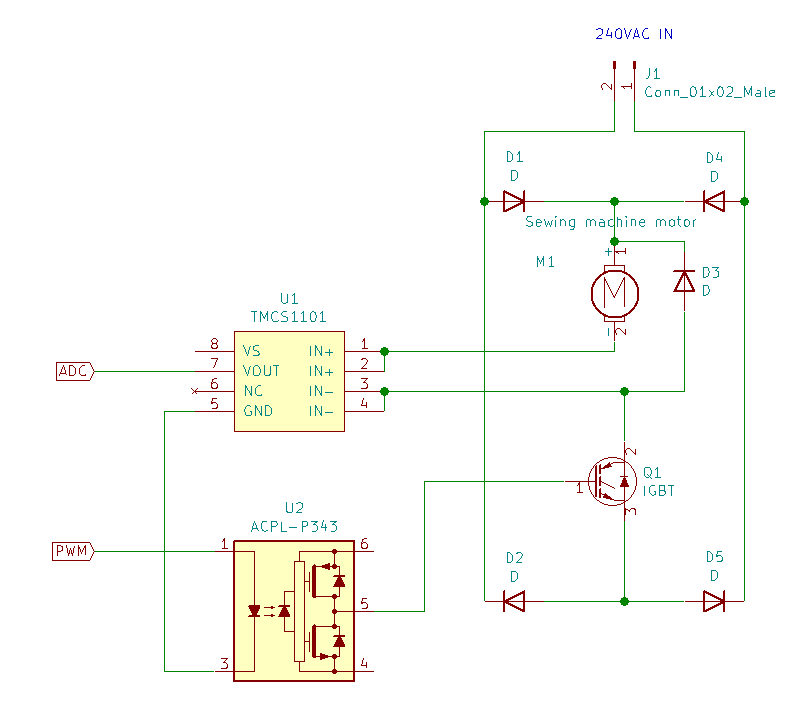 |
| Concept only - will not work. |
The ADC and PWM flags go to a microcontroller. From the known DC voltage and the PWM duty cycle you can calculate the effective applied voltage. From the current and the resistance you can calculate the voltage across the motor. The difference between that and the effective voltage is the back EMF - that is, the motor speed.
Connect a foot pedal with a potentiometer to the microcontroller, then program the microcontroller to use various set speeds for various potentiometer settings, and you’ve got yourself a motor speed controller.
I’ll be doing some experiments and collecting parts in the coming weeks. It shouldn’t take too long to come up with a completed circuit that is useful and safe.