HowTo: Solder by hand - Solder SMD ICs
Any SMD IC that has pins or pads that you can see, you can solder.
HowTo: Solder by hand - Table of Contents
Check this handy chart to find the temperature you need for this task.
This time around, I’m going to explain how to solder surface mount integrated circuits (SMD ICs.) It’s really pretty simple. The biggest “trick” is that you should always move the work pieces to make them easy to reach.
If you’ve already been through the “how to solder SMD passives” page, then you’ll find much of this familiar. As in that post, you’ll realize that it’s actually pretty quick despite the length of the text and the number of photos.
You can only solder parts with exposed pins or pads with a standard soldering iron. Parts with ball grid arrays (BGA) or hidden pads under the chip can’t be soldered with a regular soldering iron. You need a reflow oven to do them.
Steps
Here are all things it’s going to take to show you how to solder SMD ICs:
Tools
Normally you’ll only need some solder, a pair of tweezers, and your soldering iron.
If your board is pre-tinned or you are replacing a part then you will need a couple of more things.
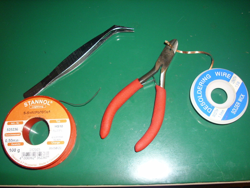
At most, you will need the following things:
- a pair of tweezers
- 0.5 millimeter solder
- solder wick for cleaning up pads
- a pair of wire cutters for clipping the solder wick when the end of it fills up
Here they are all together:
| Tools to solder SMD ICs |
|---|
 |
Positioning yourself
As I’ve mentioned before, position matters a lot when doing this kind of stuff.
When soldering SMD ICs, you have to position your hands and the PCB (printed circuit board) so that everything comes together.
The first step in soldering SMD ICs looks like this:
| Hand positions |
|---|
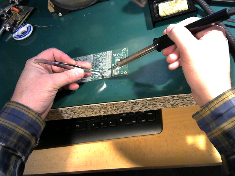 |
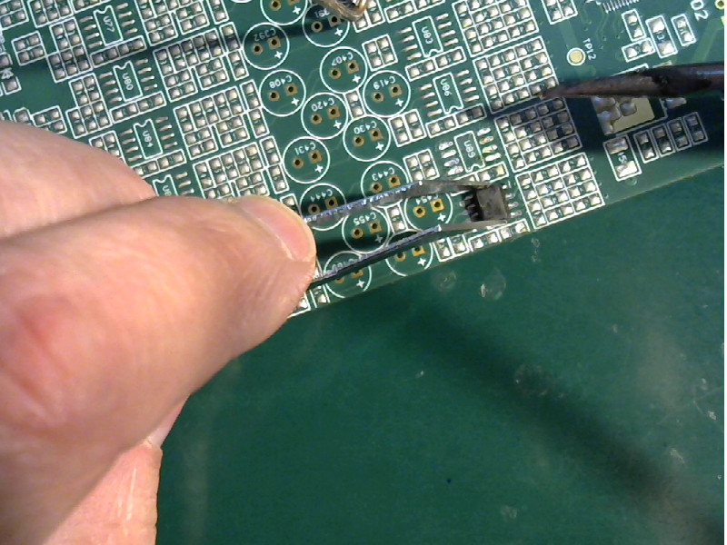
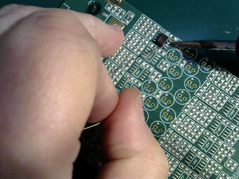
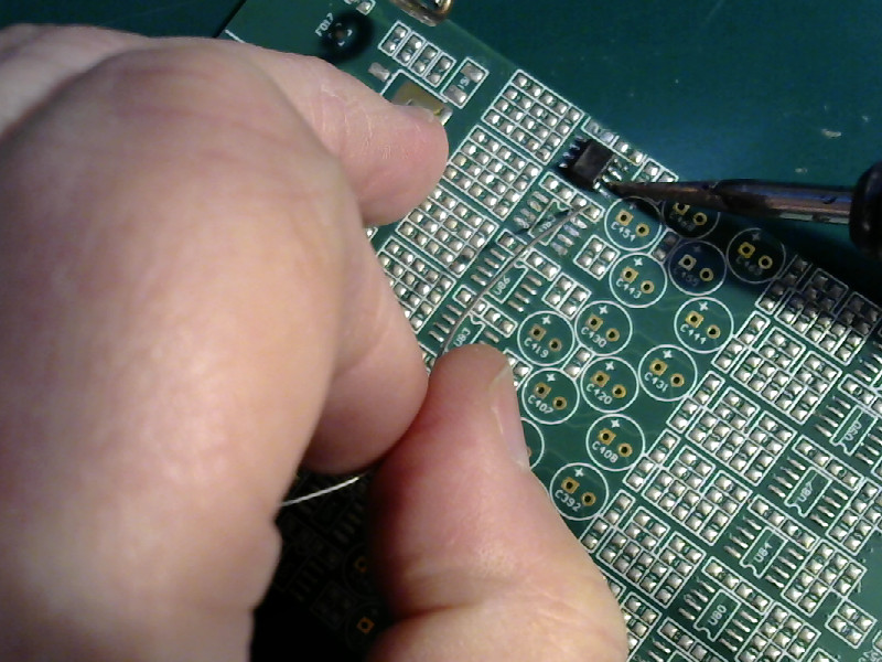
The board is postioned so that you can easily hold the chip in place with the tweezers. You should not need to twist your hand or make contortions. Pick up the part in the tweezers, then move the board around so that you can easily place the chip on the board.
As always, you brace yourself on the workbench to provide stability.
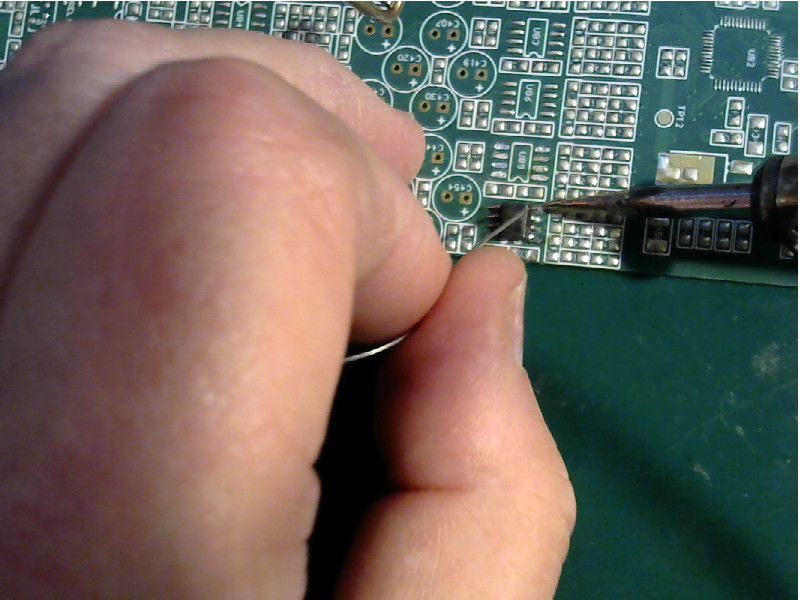
While you are lining things up, keep in mind that you want to be able to lay the point of the soldering iron down on the pads for the IC. The tip needs to be pretty much parallel to the pins.
Like this:
| Board and soldering iron tip |
|---|
 |
Part of soldering SMDs is moving the PCB around so that you can do the soldering with your hands in natural positions.
The task
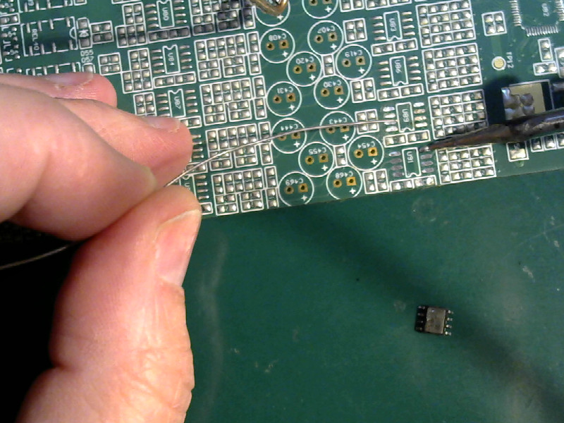
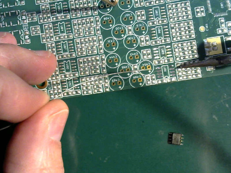
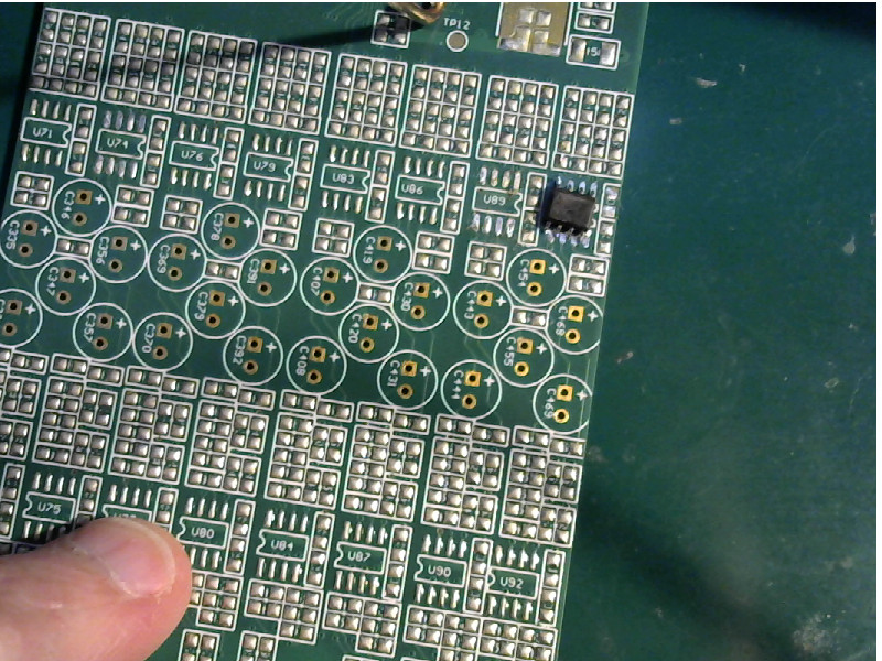
I’m going to install a small outline IC (SOIC) with 8 pins on this PCB in the space marked U91.
Here’s what they look like:
| SOIC-8 and PCB |
|---|
 |
The IC itself is 5 millimeters long and a smidge over 4 millimeters wide. The pins are 0.5 millimeters wide.
All in all, while it’s pretty small it’s still pretty easy to solder. SOIC8 is a standard size, and pretty much the easiest SMD IC style to solder by hand.
Do it to it
Step zero: Review the things you are supposed to do everytime you pick up your iron.
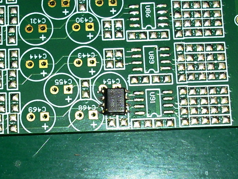
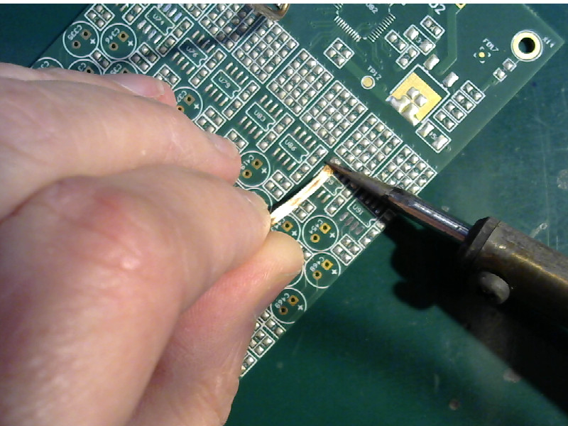
- Clean off the pads if needed.
You want all the pads for the IC to be clean. That is, they should not have a thick bump of solder on them. You want just the flat pad with just the barest thin coating of solder.
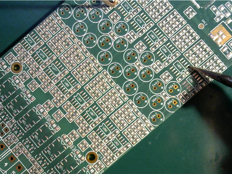
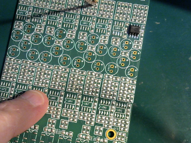
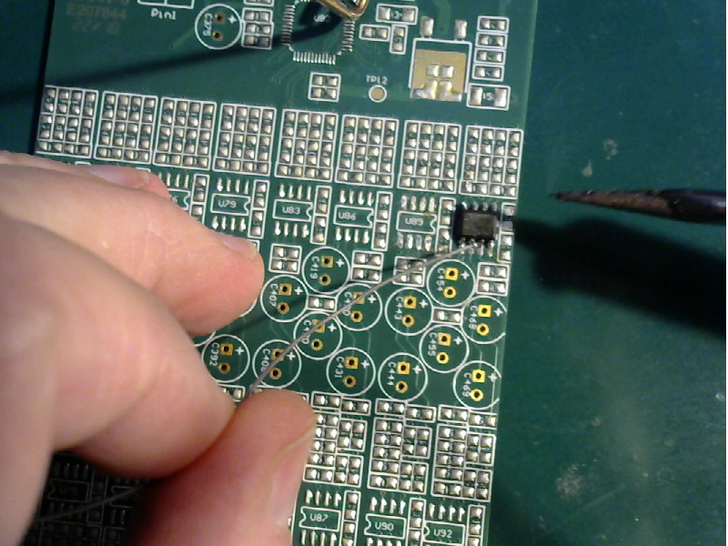
You’ll need to use the soldering iron and the solder wick to clean off the pads if they aren’t nice and flat. You can see the difference there in the first picture. The pads for U91 are already clean and flat. I’m going to remove the solder from the pads for U89 - you can see how those pads have a bump on them.
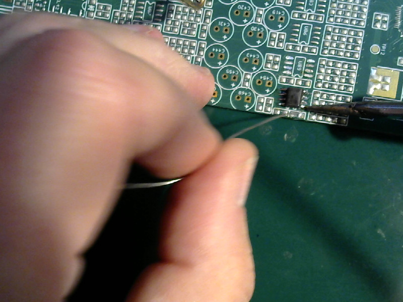
Clip the end off of your solder wick if it still has stuff on it from the last time you used it. Clip it right at the edge of the solder that’s on it. No need to waste the wick, but you don’t want a long piece of used wick getting in the way.
| Clean the pads |
|---|
 |
 |
 |
 |
 |
 |
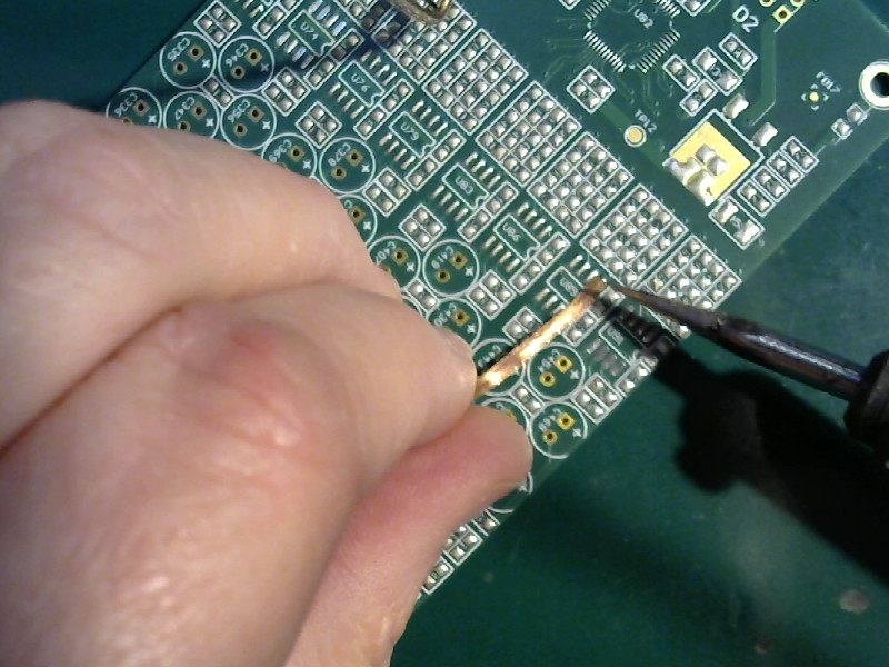
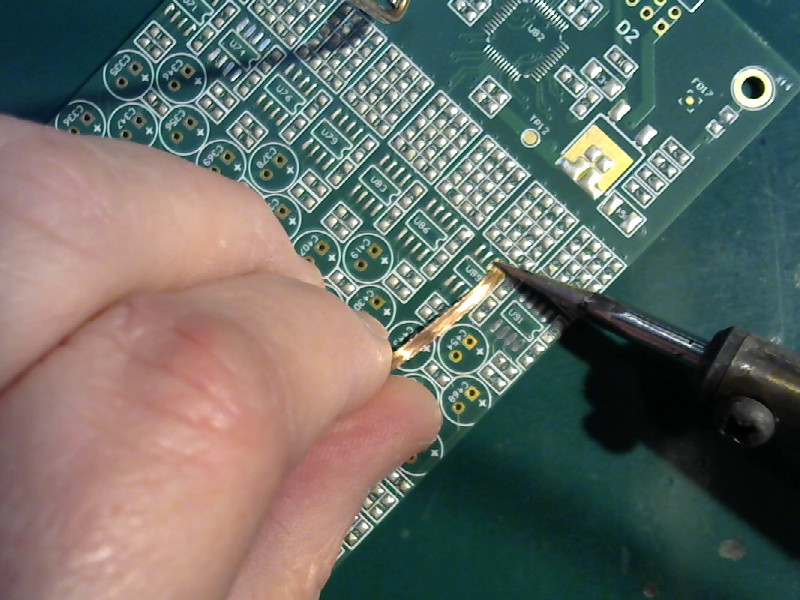
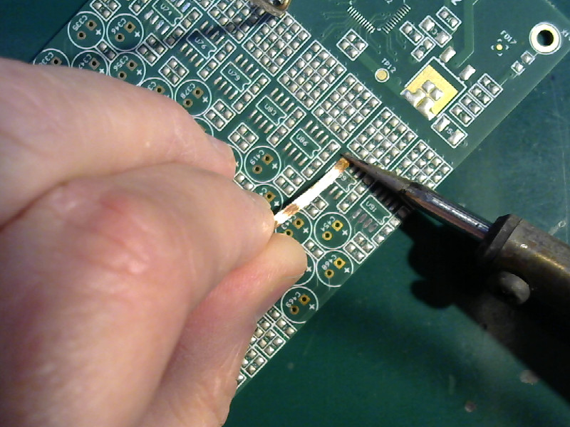
Put the solder wick down on the pad you want to clean. Get a small bit of solder on the tip of the iron, then press it down on the solder wick on top of the pad. Heat it. Wait a couple of seconds, then move to the next pad. You might have to clean a pad a couple of times to get rid of all the solder on it.
Don’t drag the solder wick across the pads. When you move the solder wick, pick it up at the same time you raise the tip of the soldering iron off the board. Raise it up high enough that the solder can’t connect it any more, then put it back down on the new spot.
The pads for U89 are nice and flat in the last picture, just like the pads for U91.
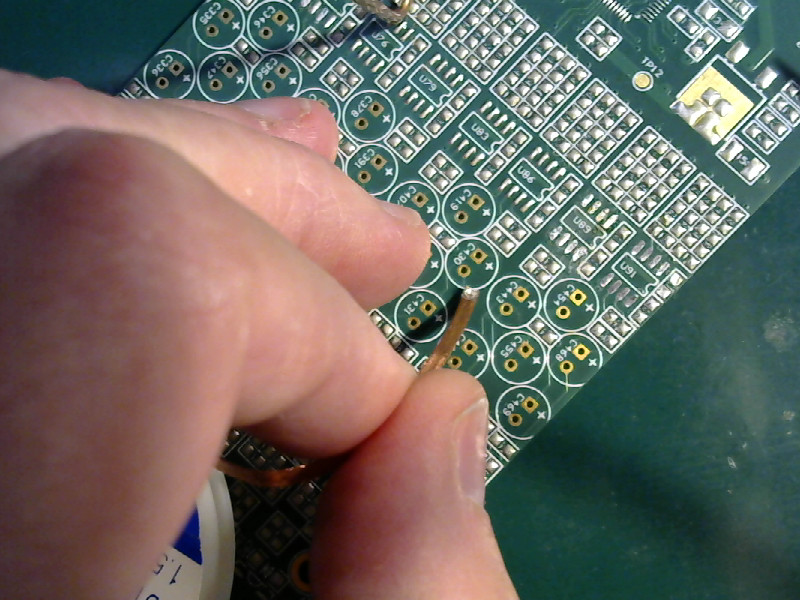
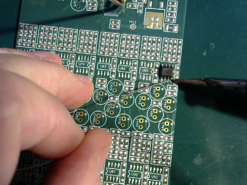
- Tin the first pad.
I made you clean all the pads, and now I’m going to make you put a blob of solder on one of them. This is the first pin you’ll solder the IC to.
| Tin the first pad |
|---|
|
 |
This little blob of solder will hold the IC in place while you solder the other pins.
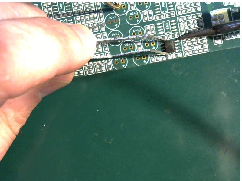
- Place the part and tack it down.
Pick up the chip with your tweezers, and place it over the pads. Make sure you have it the right way around. The “U” shaped notch in the outline of the IC on the board is the end where pin 1 of the IC goes. Check the datasheet of the IC to find pin 1 of the chip.
Line the IC up with the pads, and set it down. Touch the side of the tip of the soldering iron to the side of the tinned pad so that it touchs the pin and the pad and heats them both. When the solder melts, check the alignment and press the IC down onto the board so that all of the pins are flat on the surface. Remove the soldering iron from the joint and let the joint cool.
Like this:
| Tack down the first pin |
|---|
 |
- Check and correct the alignment.
Once the IC is tacked down, check to make sure the IC is lined up correctly
- The pins should be parallel to the pads.
- The pins should be centered along the pads.
- There should be equal amounts of free pad length on each row of pins.
This one is bad:
| Bad alignment |
|---|
 |
You have to fix any alignment problems now while there’s only one pin soldered down.
It’s easy enough. Just heat the pad, melt the solder, then move the IC around until it’s in position.
Like this:
| Fix the alignment |
|---|
 |
 |
- Solder down the next pin.
Pick the pin diagonally opposite the first one that you soldered. That is, at the other end of the chip and on the other side. Position the board so that you can easily reach that pin with the tip of your soldering iron.
Solder that pin down.
| Solder down the second pin |
|---|
 |
 |
- Solder the rest of the pins.
Now that the chip is held securely in place with two pins, you can solder all of the rest of the pins.
Turn the board so that you can poke the tip of the soldering iron inbetween the pins. You’ll use the side of the tip to heat the pad and the pins from one side of the pin while feeding in solder from the other side.
It looks like this:
| Solder the pins on one side |
|---|
 |
 |
When one side is done, reposition the board so that you can do the pins on the other side.
| Solder the pins on the other side |
|---|
 |
Remember to resolder the first pin. It wasn’t soldered properly, it was just tacked down to hold things in place.
| Resolder the first pin |
|---|
 |
- Done.
With the IC all soldered down, I made a couple of photos with my good camera.
It looks like this:
| Done |
|---|
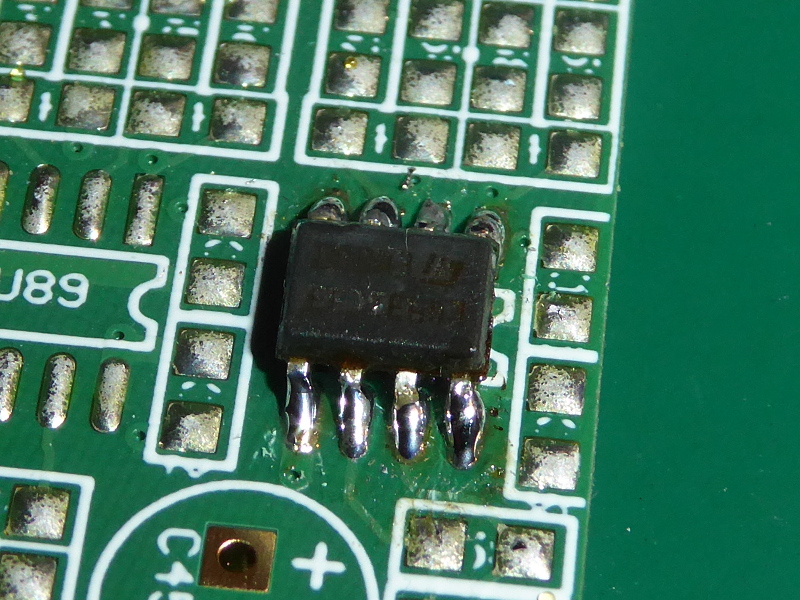 |
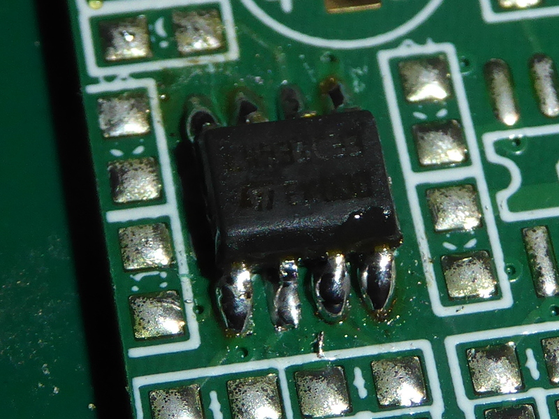 |
All the joints are clean, smooth, and shiny. All of the pins are soldered to the pads.
Always go back and double check your work when you are finished.
Watch out for:
- Skipped pins (forgot to solder one.)
- Bad alignment (so far off that pins and pads are shorted together.)
- Bad joints (sharp, jagged edge joints moved before the solder was cool.)
- Too much solder on a joint (touch the tip of the iron to the joint and remove the excess, or use the solder wick.)
Touch up anything that doesn’t look good. Do it now because it really sucks to have to go over a whole board looking for the one spot you messed up (but would have noticed if you’d checked it when you did it) when it doesn’t work.
Have no fear
Any IC that has pins or pads that you can see, you can solder.
Don’t be afraid of small parts with closely spaced pins. Don’t be scared of high pin count ICs.
I have soldered tiny µMax parts (3mmX3mm with eight pins) and PLCC 64 parts (25mmX25mm with 21 pins on each of the four sides) with this method. I have soldered thin quad flat packs (TQFP) and quad flat no lead (QFN) parts this way.
In all cases, it’s the same:
- Cleanup.
- Solder one pin.
- Align.
- Solder all the other pins.
Here is a µMax part that I soldered using this method:
| µMax MAX2015 |
|---|
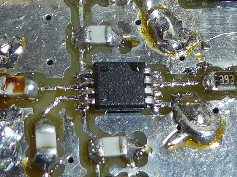 |
The part itself is 3mmX3mm in size. The traces are 0.5mm wide. I soldered that by hand using my crummy old soldering iron. Note that there’s no solder mask on that board. That chip is part of my microwave camera. It works quite well.
Here’s an image I made with the microwave camera:
| Microwave image |
|---|
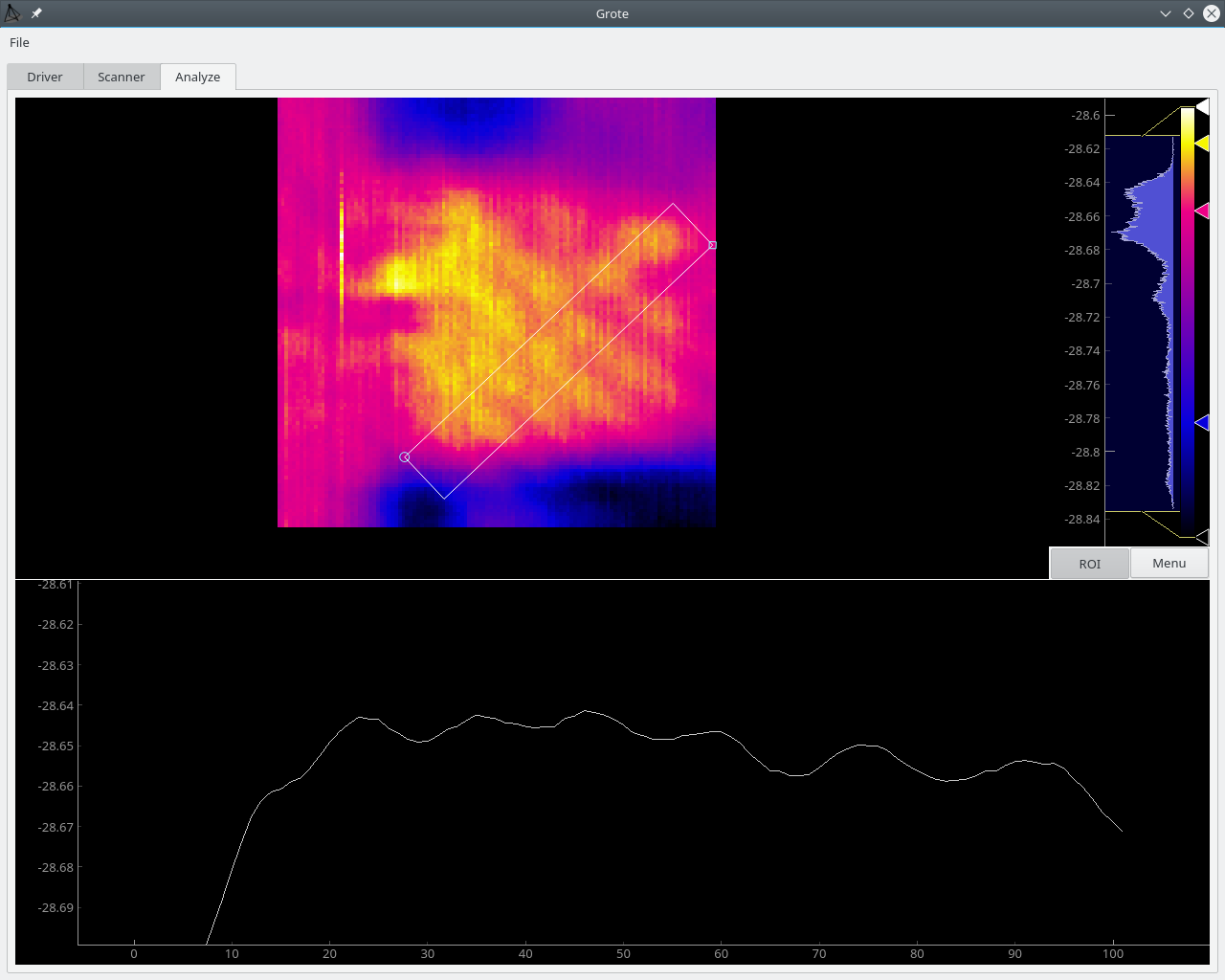 |
That’s an image of the window in my workroom made by 12GHz microwave “light.” It shows some ripples due to polarization effects across the surface of the glass, and some diffraction effects along the window sill below the glass. The “ripples” are about 0.01dBm in strength.
That kind of thing is only possible because I soldered that teensy little MAX2015 RF level detector - by hand. It isn’t difficult. You can do it, too.