HowTo: Solder by hand - Soldering simple SMD parts
Anything you can see, you can solder.
HowTo: Solder by hand - Table of Contents
Check this handy chart to find the temperature you need for this task.
It’s taken a while to get around to it, but now I’m finally going to explain how to solder surface mount devices (SMDs) by hand.
I prefer working with SMD parts these days. I find them easier to handle, easier to solder, and easier to remove if I need to change things.
There’s quite a bit of explaining to do, so I’m going to break this down into sections. It looks like a lot of stuff but once you do it you’ll realize that while it takes a lot of words to explain it, doing it is a snap. You can solder in an SMD part in just a few seconds.
Steps
Here are all things it’s going to take to show you how to solder SMD parts:
Tools
You’ll need a few tools besides your soldering iron. If you have a new, clean board that has no solder on the pads, then all you need is your soldering iron, some solder, and a pair of tweezers.
If your board is pre-tinned or you are replacing a part, then you need a couple of more things.
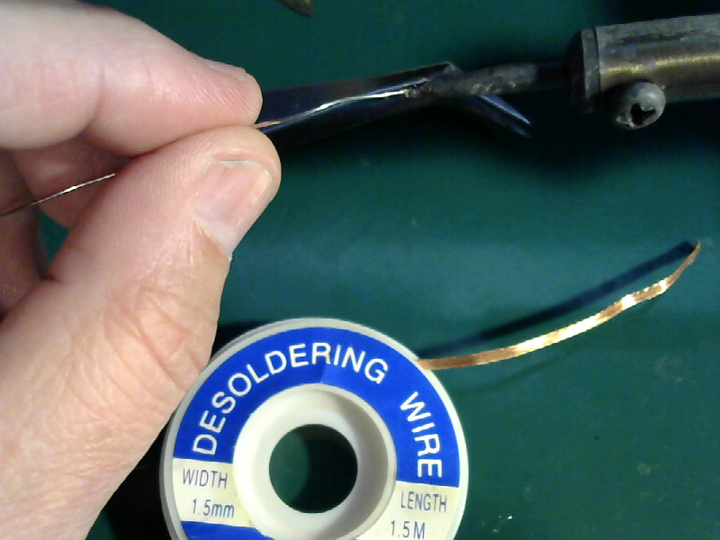
Here’s everything you need for the worst case:
| Tools to solder SMD parts |
|---|
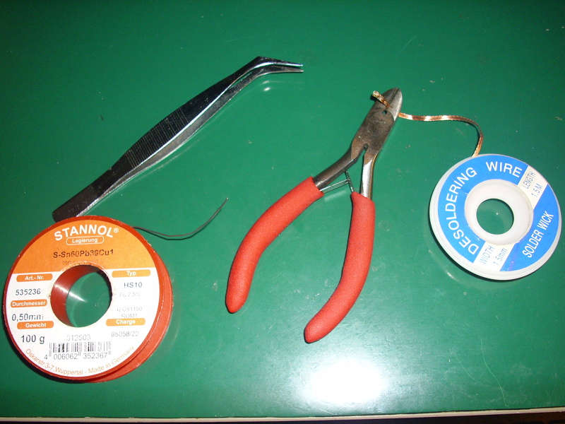 |
That’s a pair of tweezers, 0.5 millimeter solder, solder wick for cleaning up pads, and a pair of wire cutters for clipping the solder wick when the end of it fills up.
Positioning yourself
Once you get your tools gathered up, we need to get you into position.
As I mentioned in the earlier post about getting started, position is everything. It is important when soldering through hole parts, and it is doubly important when soldering SMD parts.
This is what it should look like:
| Hand positions |
|---|
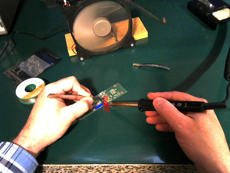 |
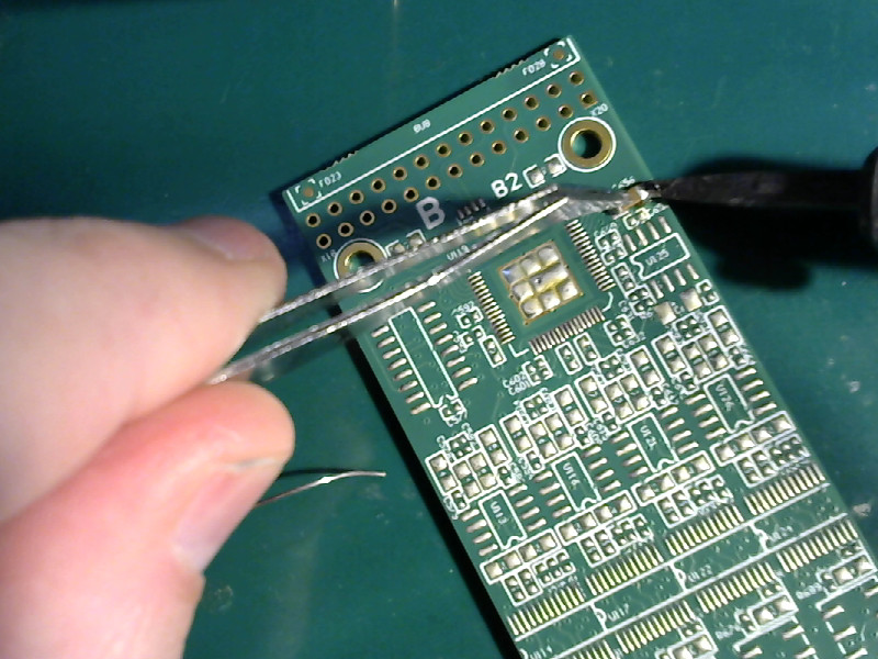
You want the tip of the iron and the edge of the SMD part to meet at a (near) 90 degree angle. In the photo it’s closer to 120 degrees. It isn’t critical. You just don’t want to have the angle too wide. You want the side of the solder iron tip to touch the end of the SMD part. The idea is to get as much contact area as possible between the tip, the SMD part, and the pad.
What is critical is the position of the left hand and the tweezers.
You must hold your left hand and the tweezers so that the SMD part you are holding in the tweezers is properly aligned with the pads on the board. The pads in the picture are too small too see, but the part should be installed parallel to the long edge of the board.
Position your left hand first. Arrange the board to fit, then position your right hand with the soldering iron.
Note that your hands are planted firmly on the work bench while doing this. The actual work is done with finger motions only.
The task
I’m going to solder a 1206 sized SMD capacitor onto a PCB.
| The task |
|---|
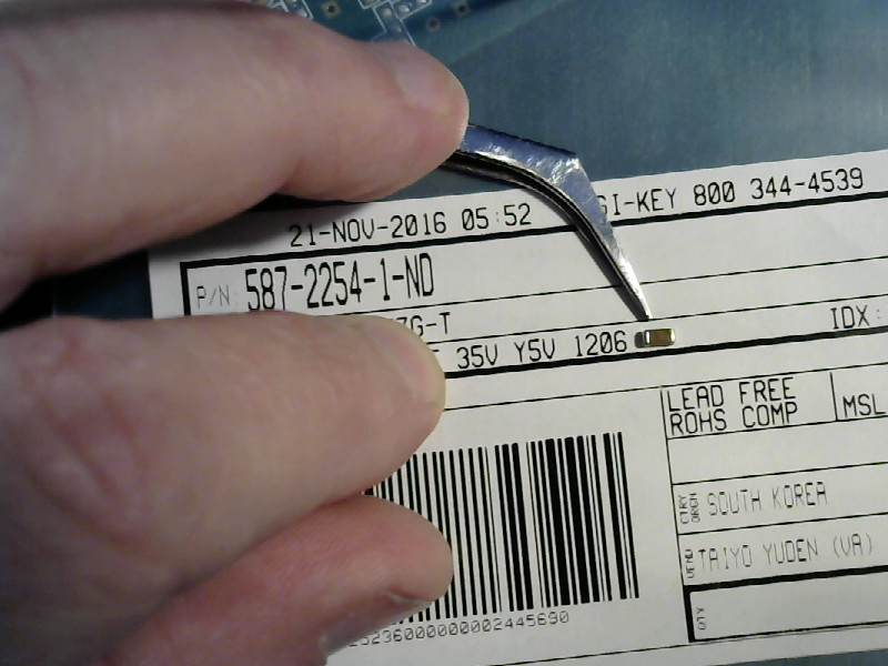 |
 |
1206 sized parts are large for SMDs. I’ll use smaller parts for the other examples.
Do it to it
- Clean off the pads if needed.
All the pads on this board already have solder on them. That’s bad. To do this properly, you want one pad to have a blob of solder on it while the second pad is clean and flat.
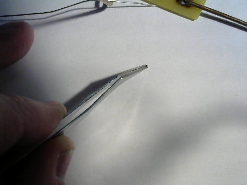
The first thing to do is to get a clean end on your solder wick. I clip the end off so that I don’t have a long tail of half used wick getting in the way.
| Clip the solder wick |
|---|
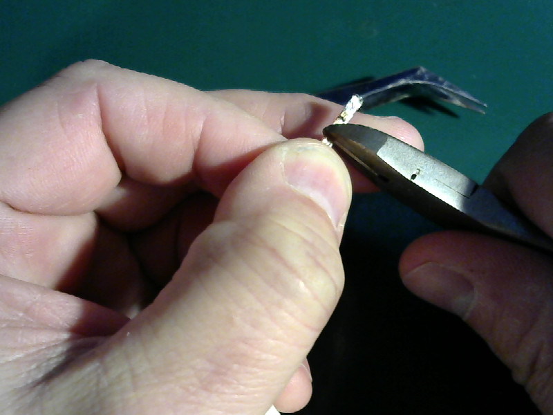 |
Clip it close to the section that’s already been used. You want to get rid of the existing solder, but you don’t want to waste any of your solder wick, either.
- Add a bit of solder to the tip of your iron.
While you are at it, review the things you are supposed to do everytime you pick up your iron.
| Tin the tip |
|---|
 |
We’re going to use that tinned spot on the tip to help conduct heat into the solder wick.
- Clean a pad.
Lay the solder wick down on the pad. Press it down with the tip of the iron and hold it in place for a couple of seconds. You should see the flux in the solder wick start to smoke. When the flux smokes, give it a second or so more and then raise the iron and the wick up off of the pad together.
| Clean a pad |
|---|
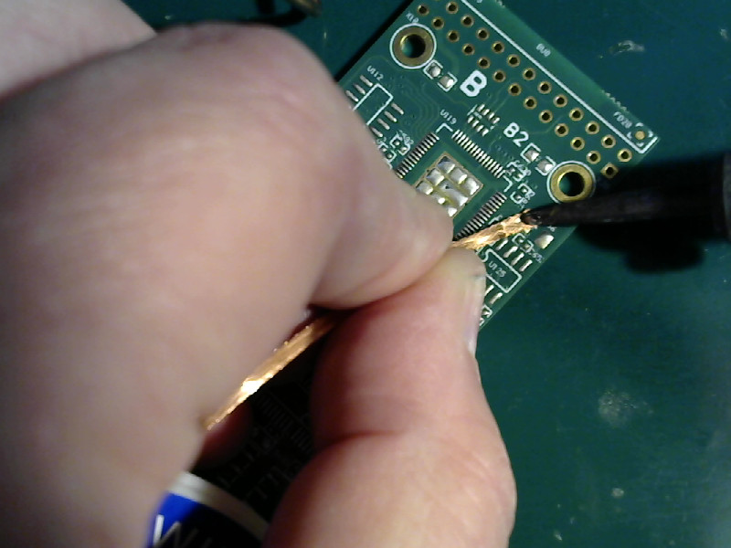 |
Never ever slide the wick across the pad. That’s a very good way to destroy the pad.
If you need to apply heat to another section of the pad, then raise the tip of the iron and move it. If you need to move the wick, then you pick up the iron and the wick then put the wick down on the new spot and apply the iron.
| Clean pads |
|---|
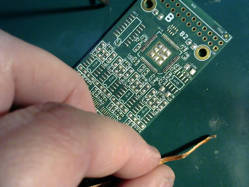 |
I did both of them. Well, it’s force of habit and it doesn’t take that long so I just did ‘em both.
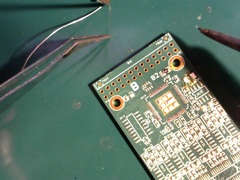
- Tin a pad.
With both pads clean (the normal case for a new PCB,) you’ll have to add a spot of solder to one of the pads.
| Tin a pad |
|---|
 |
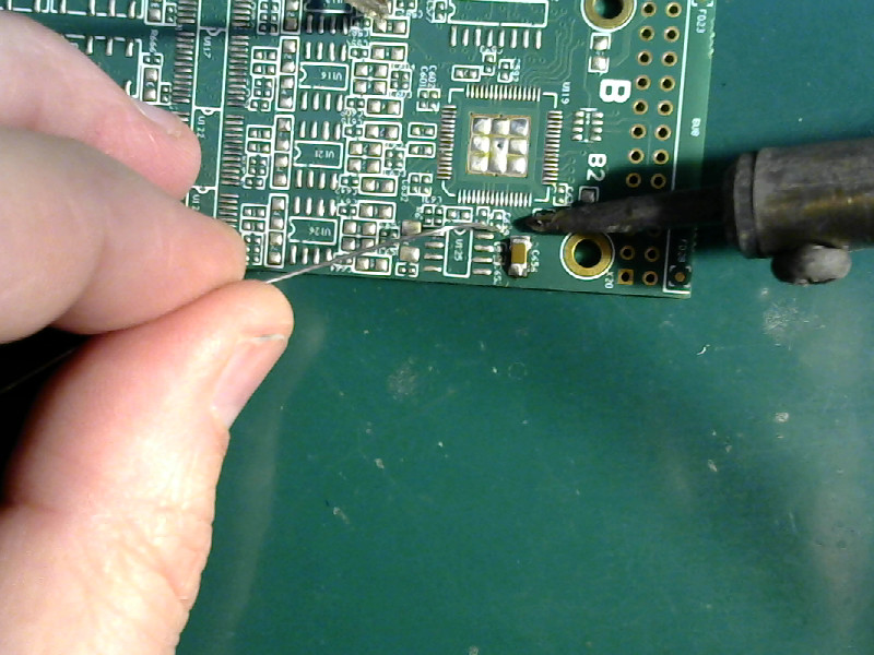
Heat the pad with the tip of the iron, and melt a small bit of solder onto the pad.
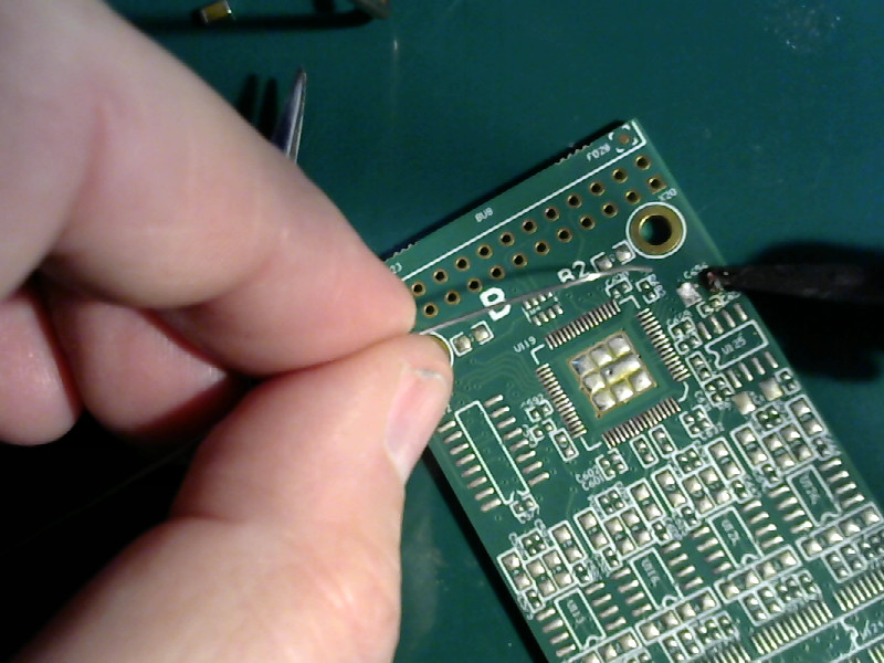
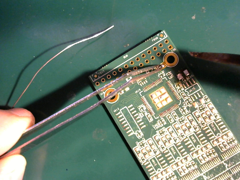
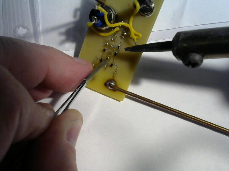
- Position the part.
You want the part to be properly placed for its pads. Position your left hand, then move the board into place with your right hand.
You’ll be soldering the pad on the right end of the part. You must put the tinned pad to the right where you can reach it with the soldering iron.
| Position the part |
|---|
 |
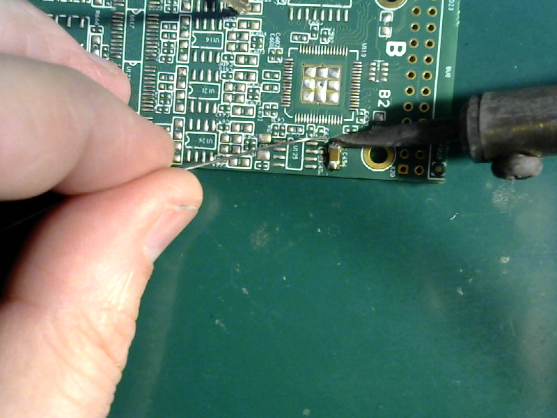
In this picture, I’ve already gotten everything into place and I have a spot of solder on the tip of the iron.
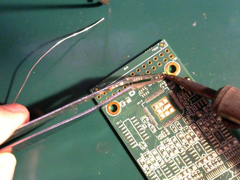
- Tack the part down.
Apply the tip with its blob of solder to the junction of the pad and the part. You want to use the tip to smear solder from the pad to the part. Do not move the part or slide it around. Once you’ve got a little solder smeared over the end of the part, remove the iron from the pad and let things cool.
| Tack the part down |
|---|
 |
The part isn’t flat on the board yet. Don’t worry. It will be.
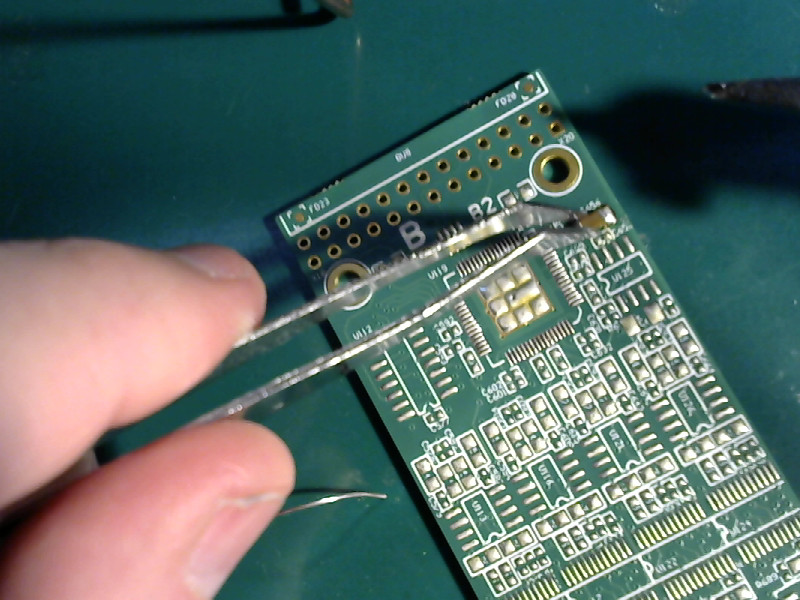
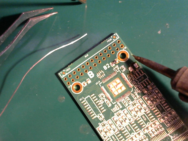
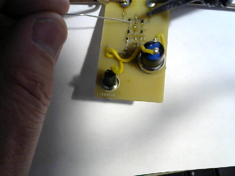
- Seat the part properly.
With the part tacked down, you can let go of it. Squeeze the tips of the tweezers together, then place them on the part. Somewhere in the middle of the top surface of the part. Put just a tiny bit of pressure on it, but don’t try to force anything.
Once you have the tweezers holding it down, apply the tip of the iron to the end that you tacked down before and melt the solder. You’ll feel a tiny “snap” as the part seats itself flat on the board. Now remove the tip of the iron from the pad and let things cool.
Those two steps look like this:
| Seat the part properly |
|---|
 |
 |
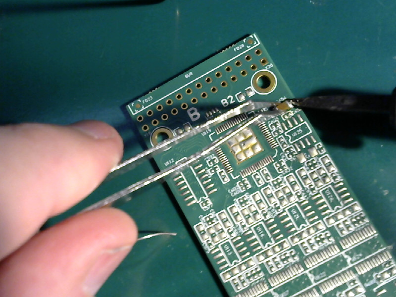
- Solder the other pad.
Now that the part is in the right place and flat on the board (and stuck down so it can’t move,) it’s time to make a proper joint on the free end.
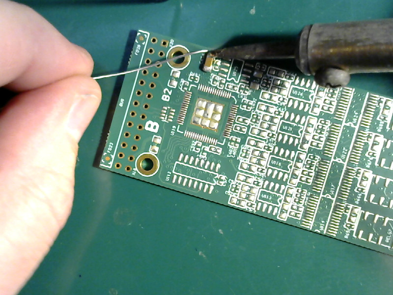
Position the board so that you can reach the free end of the part with the tip of the soldering iron.
Apply the tip of the iron to the junction of the part and the pad. Heat the part and the pad, then melt solder on the junction (not on the soldering iron tip.)
| Solder the other pad |
|---|
 |
 |
Remove the iron from the joint, and let it cool. Look it over. It should be clean and shiny and the solder should make a smooth connection to the pad and the part.
If the joint is dull or jagged, apply the iron and add a spot of solder. Check it again.
If there’s a big ball of solder connecting the part and the pad, then you should wipe the tip of the iron clean and apply the tip to the joint. Melt the ball, then remove the tip of the iron from the joint. Excess solder should go with the tip. If there’s still too much solder, clean the tip, heat the ball, and remove some more solder.
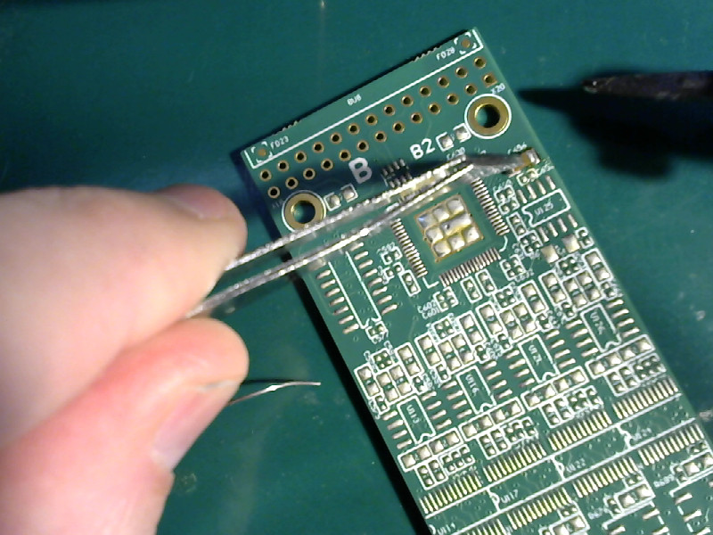
- Resolder the first joint.
The first joint wasn’t properly soldered, it was just tacked in place to hold things together. Now we need to do it properly.
Reposition the board so that you can get to the first joint with the tip of the soldering iron. Apply the tip of the iron to the joint, and melt a bit of solder on the joint (not on the tip of the iron.) Remove the iron, and inspect and clean up the joint just like you did the first one.
| Resolder the first joint |
|---|
 |
- Done.
If you’ve followed along with me, you will have a 1206 sized part neatly soldered to a PCB.
Mine looks like this:
| Done |
|---|
 |
 |
Handling problems
There’s really only one bad problem that can occur while doing this.
Sometimes you’ll wiggle at the wrong moment and get your part out of alignment. That can only happen when you are tacking down the first joint.
Since there’s only one end soldered in place, it’s pretty easy to fix.
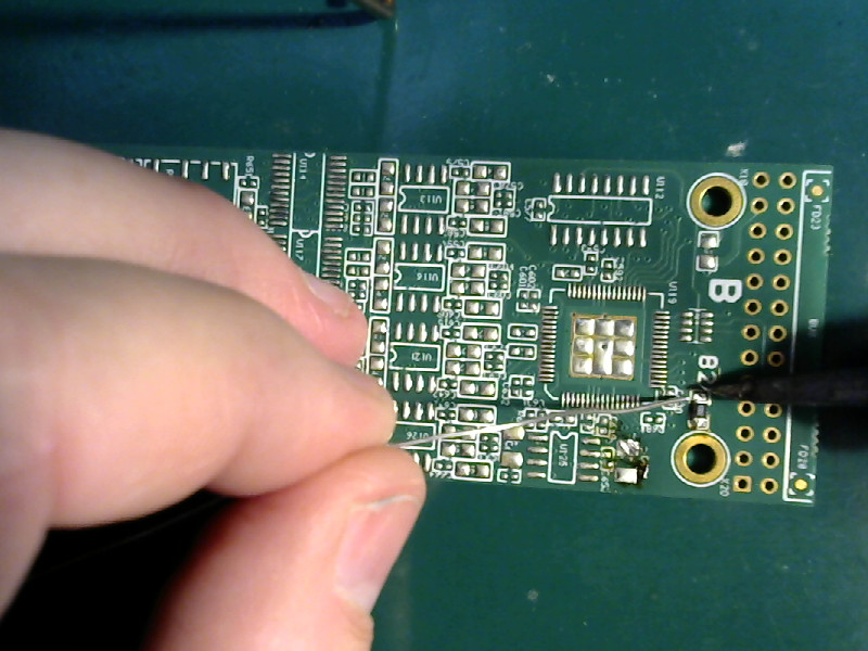
I’m going to run through installing a 0805 sized part (that’s smaller than the 1206) and show you how to fix a misaligned part. This time around I won’t add as many comments - it’ll be pretty much just the pictures and an explanation of how to fix the mistake.
| Doing a 0805 part |
|---|
 |
 |
 |
 |
Oops! Got it crooked.
No sweat.
Grab it with your tweezers, and apply the tip of the iron to the joint.
When the solder melts, use your tweezers to line the part up. Make sure it sits evenly on the pads.
Remove the iron and let the solder cool before removing the tweezers.
| Straighten it out |
|---|
 |
| Fixed |
|---|
 |
Now continue with the rest.
| Finish up the 0805 |
|---|
 |
 |
 |
Have no fear
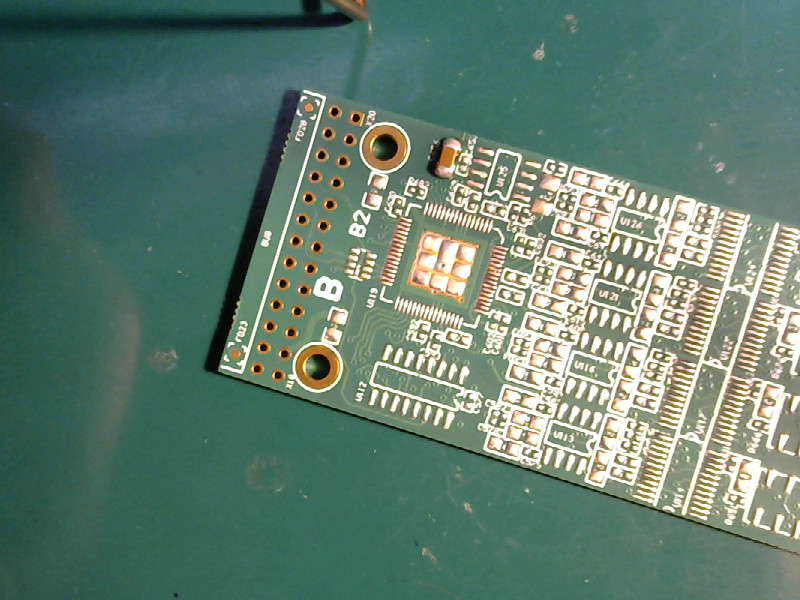
You can use this technique on any SMD component, in any size. 0805, 0603, 0402, and 0201. If you can see them you can solder them.
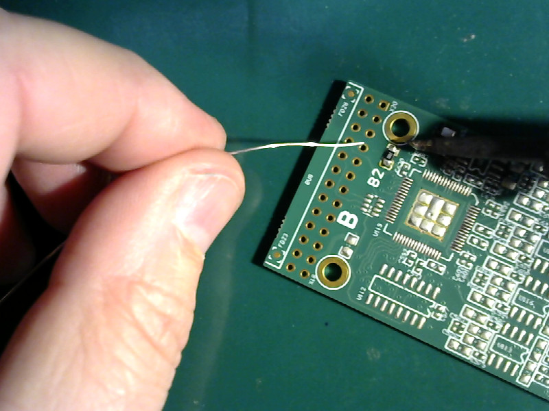
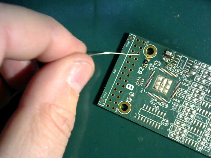
I’m going to run through installing a 0402 sized component. No comments. I just want to show you that it can be done. I was going to show how to solder 0201 parts, but I messed up when making the photos and used a 0402 part - and soldered it onto 0201 pads.
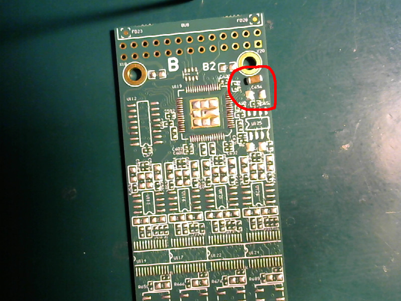
| Doing a 0402 sized part |
|---|
 |
 |
 |
 |
 |
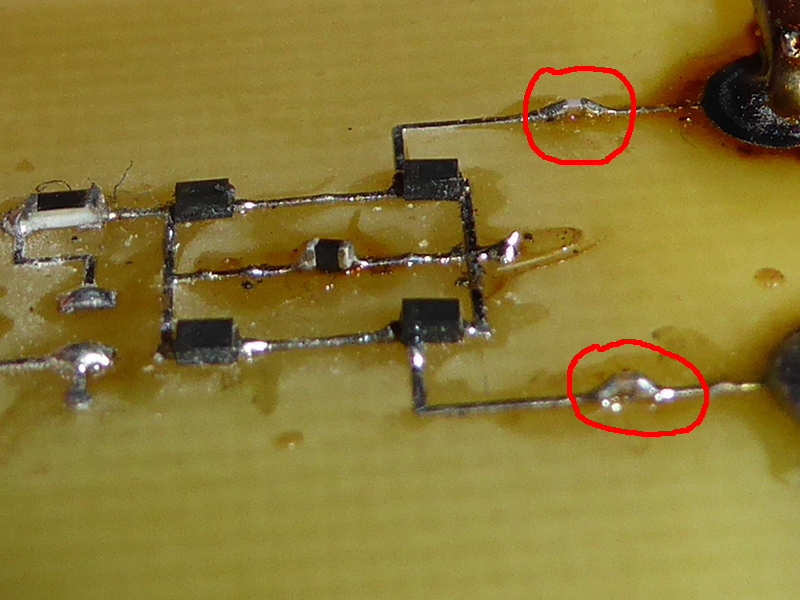 |
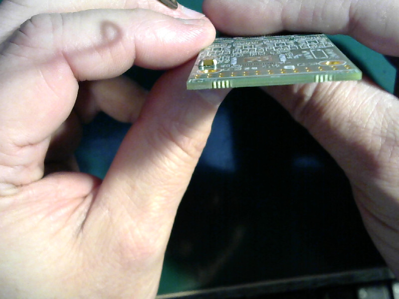
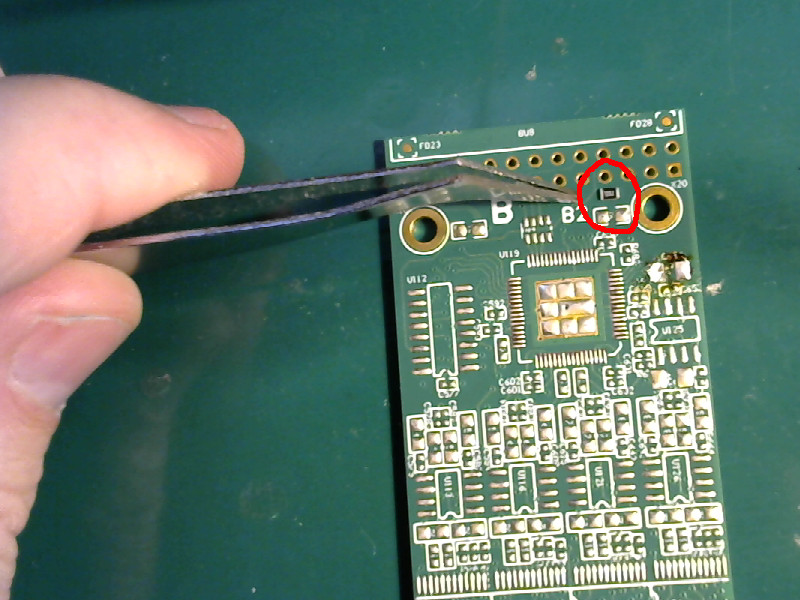
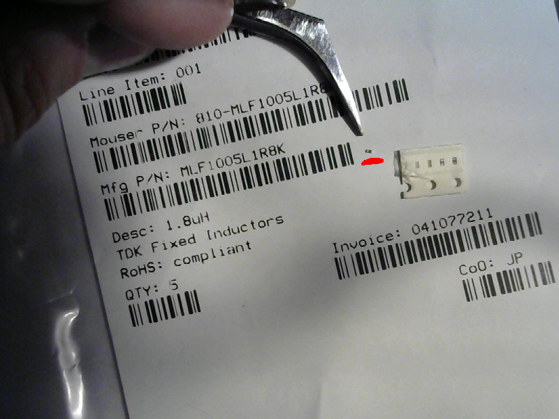
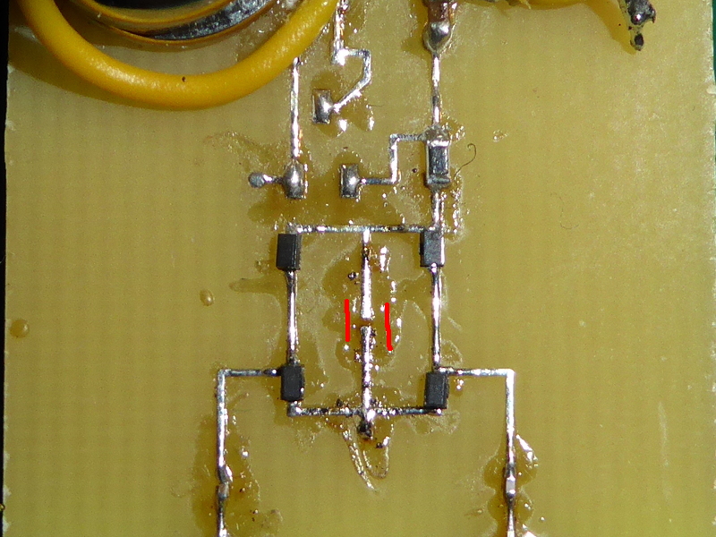
There’s two things to tell you about that last photo:
- I had to get out my good camera to make that picture because EyeGore doesn’t have enough resolution.
- The red circled spots are 0201 sized parts that I installed on that board a few months ago.
I did that 0402 sized part with a worn down tip and the board was flopping loose on the work bench - it was held down only with my fingers while I was working. That’s an extreme example to show that not only is it easy to solder SMD parts, but that you can do it in less than ideal conditions.
Like everything, it does take practice. Start with 1206 sized parts and work your way down to the smaller stuff.
Remember:
Anything you can see, you can solder.
A final word:
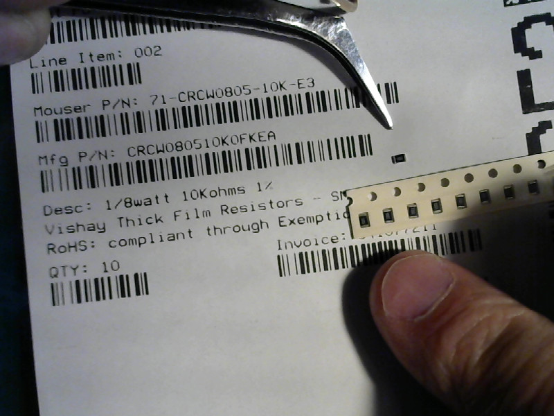
Never have more than one value of passive component open and on your work bench at a time. SMD capacitors aren’t marked. Neither are inductors. Resistors are marked, but only 0805 size and larger.
If you get different values mixed together, you will have problems. You can’t tell them apart when they are installed, and that can cause all kinds of hard to figure out problems with your circuit.
You could check the values with a meter while the parts are still on the bench, but it is a pain.
The safest thing to do is to install all of one value on your board, then pack up the remaining parts and put them away before doing the next value part.
Make your life easy. Only one value of parts out on the bench at any time. Your nerves will thank you.